01 February, 2012

Stress Patterns

Here are some more pictures taken at the ASE show. 
These show the stress patterns which are visible in our set square after it is exposed to polarised light, for these images we have used a polarised light source from a standard LCD computer screen instead of our normal lightbox.

The LCD screen has a polarising film in it at 45 degrees to the vertical so only a single sheet of polarising film is needed to produce an effect.

Set square with out Polarising Film.

Stress patterns within the set square viewed through a sheet of Polarising Film.

10 January, 2012

Demo of the Stirling Engine


A short demo from our stand at the ASE exhibition in Liverpool last week.
This is our model of a Stirling Engine, which is running from a cup of hot water. 
This model is mostly made out of cardboard with a few metal pieces.

14 November, 2011

Amazing World


I have found an amazing video cropping up on my news feed a lot in the last few days and decided to take a look at it.
Well I cant keep it all to myself it is an amazing piece of footage from the International Space Station. 


What a truly amazing planet we live on.


I do just wish this as a little slower so I could appreciate the detail a little more.


Earth | Time Lapse View from Space, Fly Over | NASA, ISS from Michael König on Vimeo.


Time lapse sequences of photographs taken by Ron Garan 
fragileoasis.org/​bloggernauts/​Astro_Ron and the crew of expedition 
28 & 29 onboard the International Space Station from August to October,
2011


List of clips:
1. Aurora Borealis Pass over the United States at Night
2. Aurora Borealis and eastern United States at Night
3. Aurora Australis from Madagascar to southwest of Australia
4. Aurora Australis south of Australia
5. Northwest coast of United States to Central South America at Night
6. Aurora Australis from the Southern to the Northern Pacific Ocean
7. Halfway around the World
8. Night Pass over Central Africa and the Middle East
9. Evening Pass over the Sahara Desert and the Middle East
10. Pass over Canada and Central United States at Night
11. Pass over Southern California to Hudson Bay
12. Islands in the Philippine Sea at Night
13. Pass over Eastern Asia to Philippine Sea and Guam
14. Views of the Mideast at Night
15. Night Pass over Mediterranean Sea
16. Aurora Borealis and the United States at Night
17. Aurora Australis over Indian Ocean
18. Eastern Europe to Southeastern Asia at Night


20 October, 2011

Space debris


This Sunday another Satellite is due to come crashing down to earth. The German ROSAT satellite finished its service in 1999 after nearly 7 years more service than was originally planned. It was planed that the satellite that was launched in 1990 would function for 18 months but was only shut down in 1999. ROSAT was designed in the 1980's when the end of life of satellites was not really considered so it was not built with its own propulsion system, like modern satellites, which enables their re-entry conditions to be controlled to ensure that they land in an uninhabited area of the globe. 

The chance of this satellite causing harm to anyone is higher then the previous uncontrolled decent at 1 in 2000. Some confusion was noted in the run up to the UARS decent, this is not the chance that you as an individual will get hurt, but that someone somewhere on the planet will get hurt. 

The satellite is predicted to fall somewhere between 53° N and 53°S which unfortunately covers most of the worlds landmasses. The exact location or timing cannot be predicted at the moment due to changes in the radiation from the sun causing the upper atmosphere to expand and contract changing the 'pull' of the atmosphere on the satellite. 
Increased solar activity expands the atmosphere and increases the 'pull' advancing the descent of ROSAT by a small margin each time. 

Following ROSAT_Reentry on twitter helps to get an understanding of when the satellite will enventually fall, the current prediction is Space-Track #ROSAT Predicted Decay 2011-10-23 05:03 GMT ± 48 Hours as @ 2011-10-20 08:06 GMT

With a window of +/- 48h there is still a large margin of uncertainty. But it does look likely that the satellite is no longer going to be visible from the UK, unless the descent is at the right  time so that some  of the burn up in the atmosphere is visible. 

In other space related news, look to the skys this evening as there is supposed to be some Orionid activity. Meteors to you and I :D

15 September, 2011

How To - Reusable Coffee Cup Sleeve

A quick how to to make a reusable sleeve for take away coffee cups. 


I have made a number of these in different mediums before, I knit them and sow them but I know that these skills are not available to all so here is a more accessible version of the reusable sleeve. It's is made from foam rubber sheets - which are easy to work with and come in a variety of colours.


This is a simple pattern which uses a tab to keep it together and so can come apart to store it in its flat form in a bag or folder. 


For this project I used a pre existing sleeve as a template and added a tab and slot to secure the ends together. 


Instructions:


1) Open out the existing sleeve to get a pattern:


2) Work out the best placement on the foam sheet to ensure the minimum wastage:


3) Draw around the sleeve in a Biro or other thin pen:


4) Trace the outline in a thicker marker, adding a tab to one end and a cutout to the other. You need to make sure that the width of the cut out is the same size as the connection for the tab:


5) Cut out the design. The foam sheet is easy to cut with a standard pair of kitchen scissors. It is better to leave the tab too large to start with rather than cut it too close and find that the sleeve wont stay together: 


6) Connect up the two ends. Recutting the tab smaller if necessary till you get a good fit:


7) Place holder around your hot beverage. Or pre used cup which is being used as a template, as the case is here:


8) The foam rubber will take decoration of many types. Here I have drawn a simple design on in permanent marker. Finally a use for my sisters stash of sharpies! :p 


9) The beauty of the flexibility of the foam rubber and this closure method is that you can create a reversible sleeve. Decorate one side in a funky manner and have the other side plain or with your company name/logo on it so that the sleeve will serve for both social coffees and those with important business meetings: 


And voilà one simple way to ensure that you don't burn your fingers on a hot coffee and you make a small little difference in the number of coffee sleeves which make it to a landfill, and reduce the number of trees needing to be cut down. 
If you are not so bothered by the environmental impact of the take away coffee it is still a nice way to personalise the coffee on the go experience. :D

17 August, 2011

What do the spectrums mean?

Previously I have shown images that I have taken of the spectrum captured using my home-made spectrograph and plain and simple diffraction grating slides, but what do the images captured actually mean?


I will start by explaining what visible light is in relation to the electromagnetic spectrum then


Visible light:
This is one section of the Electromagnetic (EM) spectrum which is visible to the human eye. Light (and other electromagnetic radiation) travels as a wave but unlike sound energy, which vibrates the air particles to transport the signal away from the source, it does not need particles to travel through since it is a vibration of the magnetic and electric fields. This enables light to reach us from the sun, through the vacuum of space. 


This image shows the different wavelengths of the visible light spectrum. Red light has a lower frequency (therefore a larger wavelength ~700nm) and violet light has a higher frequency (smaller wavelength ~400nm), outside of these wavelengths the human eye is unable to pick up the signal contained by these waves. 


Colours are perceived by the eye due to different proportions of the different wavelengths being absorbed and reflected by different surfaces. A surface which appears Red will be reflecting the EM radiation which corresponds to the red section of the spectrum whilst absorbing the other wavelengths. 
Colours which are not a direct wavelength colour (Red, Orange, Yellow etc) can be made up by mixing light of different wavelengths. 


'White light' is made in a similar fashion and is composed of light of all the different wavelengths. 


Images of the spectrum:


The fact that white light is made up of the whole spectrum can be shown simply by shining a light through a prism which uses the difference in densities of the glass and air to bend the light. Light of different wavelengths reacts to the change in densities by a different amount so they bend at different angles causing the spectrum to spread out. 


This process is replicated in the diffraction grating but in a way that means it is possible to have a 'flat' material rather than the traditional bulky prism. 


The images I took previously of the spectrum from an incandescent bulb shows the same complete coverage of the spectrum and all at a similar intensity.
Whereas the spectrum of the energy saving light bulb shows bands of higher and lower intensity throughout the visible spectrum. 
The differences between the two spectra are due to the processes that the bulbs use to create 'white light' (I will discuss this in a later post). But what do the actual spectra mean?


Well, certain elements will give off light at specific wavelengths, called an emission spectrum, which is controlled by the actual structure of the atom in question. 


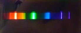
here is an example of an emissions spectrum for Carbon:


This shows the intensity peaking at specific wavelengths. Using spectroscopy scientists can ideantify the elements in a substance. This is mostly used in astronomy, where scientists will use the emissions spectra for stars or distant galaxies to identify what elements are present and giving off light.

08 August, 2011

Is back in business

I am back in business now :D

Hopefully I will have a number of new things to go on here in the coming weeks.

Till then...

02 November, 2010

LED Torches and contrast.

Trying to find a decent torch that can be used by my friend who is a marine engineer is proving to be a bit more of a challenge than first thought.
The criteria are that it is:
Tough - it needs to be able to withstand a fair amount of grief,
Waterproof - it will come into contact with a fair amount of water and oils.
Small enough to fit in boiler suit comfortably - not be too heavy or large.
Be able to use rechargeable batteries with out loosing brightness.

With this in mind I thought that an LED torch would be a good idea but having spoken to him again recently he claims that white LEDs have a higher green light content than normal bulbs and that this makes it harder to detect contrast, so I have decided to be pedantic and test this. 
I plan to try and get images of the spectrum of the typical bulbs found in normal torches and then the spectrum of common white light LEDs and see if there is any difference and if there specific makes of LED that are closer to 'normal' light which would make for better bulbs in torches. Additionally if I have time to look into filtering the light to make it into a better spectrum for use in detecting contrast etc.

To be continued...

16 August, 2010

'Home Made' Spectrograph

Today I am still playing around with the diffraction grating and working out how to create the typical spectral lines that you expect when looking into the spectra.
To do this I need to sort out the problems that I have had with my original Photos:
  • Trying to hold the diffraction grating flat and not have it bend when taking the photos.
  • Trying to have a background that doesn't wash out the colour of the rest of the spectrum (black) with out having the light from the spectrum being too bright and wash out the colour in it when taking photos with a not very advanced camera. 
  • Cutting down the light that is subsequently split so that the spectrum is more easily recognised. 
 To do this I looked into other home made spectroscopes that are talked about on the Internet and decided that I would give making one of these a try. So using an old box that I had I glued one end shut so that it only had a small split in it to let the light in.
For this I am using a 1000 line/mm diffraction grating slide so I drew around the outside and inside of this on the other end of the box, since I am planning to create the ability to change slides (500 line/mm and 532 line/mm twin axis are also available). I cut out the area that corresponds to the inside of the slide (where the diffraction grating is). This has to be cut out of both of the layers of flaps on this end of the box so that you create a hole that the light can go through.
Additionally I then built up a 'holder' that would keep the slide in place by layering two sections of cardboard up, the lower one which lines up with the outside of the slide and the top layer that overlaps this.

Once this has been built the fine tuning needs to be done so that all the extraneous light is blocked out and is only received to the grating from the slit in the end of the box. To do this I used electrical tap to cover up the corners of the box, where light was making its way in.
After this you can look through the grating to see the spectrum of a light source. To do this you aim the slit at a light source and look into the 'hole'.
If you have cut the hole directly in line with the slit then you will need to hold the apparatus at a slight angle to be able to see the spectrum that is given off. 

Uses of the Spectrograph:
Not all light that looks 'white' is the same. Looking through the spectrograph at a light source will give off a specific spectrum, for example looking at sunlight will produce a continuous 'rainbow' spectrum, which is very similar to the spectrum given off from an incandescent bulb in the visible wavebands.
* Our eyes can only pick up a specific part of the whole spectrum and sunlight is made up of a lot more of the 'invisible' parts of the spectrum than incandescent bulbs are. For example UV radiation is present in sunlight but not in bulbs, hence why we tan outdoors but not indoors*

 Here is the spectrum given off by an incandescent bulb, photographed with the spectrograph that I made earlier in the day. This has been taken with my iPhone, which explains why the quality isn't perfect.
Here is the same set up but taking a photograph of the spectrum given off by an energy saving bulb. Notice how the spectrum is no longer continuous but is made up of strong signals at specific wavelengths.
Other interesting Lights to look at range from, Sodium street lights, fluorescent lights, LEDs the list is endless, Also if you are very careful you can look at the spectrum given off by different flames (but please take care when doing this)

A few more photos are on Picasa Web Albums and more will be added as they are taken (hopefully with the better camera, and of more light emissions)

12 August, 2010

Fixing Nicrome Wire to use as a Cutting Edge


So this post doesn't come with any colourful pictures but is a problem that I have come across at work recently and have had to put my mind into coming up with an answer and then the more complicated problem of trying to communicate this to other people.

Nichrome wire is a wire that is often used for its property that when you put a current along its length it will heat up, it is used in heating elements and also for the cutting of polystyrene such as in the making of ceiling tiles or just to cut interesting shapes out of this easily accessible material.

But how do you secure a hot wire enough to apply a current to it and to then keep it under enough tension to use to cut through polystyrene?

Since when a current is applied to the wire it will heat up and this can cause the wire to expand and so any length that has been fixed at both ends would end up being loose and would not cut a straight line. 

So the challenge is to secure the wire and apply a current to it in a way that allows the tension on the wire to stay constant as its length changes. Here the application of a tensioning device such as a spring is an obvious choice but applying the current to this set-up is an interesting problem. 
Securing the wire at one end and then using a spring at the other end of the wire will keep the wire under tension and securing the power input ‘inside’ of these two fixings will mean that the fixings are not part of the circuit and will only be receiving heat from transfer down the wire.

Using this method the wire itself is secured and then the current is applied in a second connection. This could be improved by additionally supporting the wire so that when there is tension on the wire from cutting the polystyrene this doesn’t relay back to the fittings and twist these at all. To add this extra precaution the wire should be lead around a set of bearings.


When using this method it is possible to add the current to the system at the point of the pulleys but if this is done special consideration must be made to make sure that they still rotate other wise the wire will be worn through as it expands and contracts rubbing against the turning point.
 

11 August, 2010

Photos of Light spectrum through diffraction grating

In addition to my Polarising film set up I am trying to create a set up to show how light is split when passing through diffraction grating. So I picked up a grain of wheat bulb and set about trying to work out how would be best to show this.
Unlike my polarising film photos the set up was not already created, so these photos are from my first round of trials and there will be more when I have managed to incorporate the modifications that showed to be necessary from this round.

I did initially try a round of photos with an E10 bulb and a white background but this was too large a light source and the white background meant that it washed the colour out of the spectrum and provided problems when trying to clean up the images.

So my first modifications resulted in using a black table as a background and taking the photos in the dark (except for the bulb) to reduce the amount of background light, and using a grain of wheat bulb since this would produce a much smaller light source.
I am yet to decide if taking photos in a dark room is a good idea or not since when the light source is in the photo it 'burns out' due to being so much brighter than the surrounding image.


This image shows how bright the light is but also shows the colours produced quite well.

This was only the second photo I took with this set-up and here I will have to apologise for the quality of the photos since it was only a trial they are only taken using my iPhone camera.


This shows how the main part of the spectrum is 'burnt out' since it it much brighter but it also shows the range of colours that the light produces and shows the start of a second 'tail' out side of the initial spectrum. Here the light source is to the left of the image.


Another problem that shows up on some of these images in that the Diffraction Grating that I used was just held by me in one hand so it had a tendency to bend resulting in bent spectrum lines this will be rectified in future photography sessions by mounting the diffraction grating before using it. I will also mount the camera since these images are taken in the dark resulting in a long exposure time so to create a higher quality photograph mounting the camera would reduce the blur created by movement of the camera.

The first set of images were taken with either 500 or 1000 lines/mm Single Axis Diffraction grating but I also had 532 lines/mm Twin-Axis Diffraction Grating to play about with and this produced some much more interesting images


Here the spectrum is split as
it was before but due to the diffraction grating having two axis the light is split in many directions producing this interesting star effect.

To view more of the initial photos see them here

10 August, 2010

Fun with Polarising Film...

Polarising film is an interesting material to play around with since it can produce amazing patterns and colours when combined with the right materials.

At work we have a light box that is fitted out with a square of polarising film the same size and the top of the box, this produces a polarised light source. Normally this light box is used in conjunction with a sheet of clear plastic covered with strips Selotape (cellulose tape) at different angles, which produces many varying colours due to the interaction of the natural bio-refringent properties of the tape and the polarised light, to see the effect of this you need to be looking through an additional sheet of polarising film.

Here is an image taken with this set-up:


The polarising properties inherent in the tape also occur naturally in minerals such as mica. Removing the Selotaped layer and replacing it with chips of mica produced similar results, with the main difference that it was possible to see different colours in one chip meaning that the polarising properties could change across one chip where as with the tape the only variation was the angle of the tape. In the mica the changes are to do with angle and also the thickness of the layer and how the minerals were layed down.

This image shows the change in colour between different chips and across the same chip:


Here is a close up of an individual chip showing its variations:


Additionally this polarising film set-up can be used to show the stress patterns occurring in plastic objects. Using this set-up I have looked at clear plastic ruler and a clear plastic drawing pin. When looked at with polarised light and a polarised filter the stress patterns evident in the material show up as changes in the colour of light. In these images the stress patterns are ones inherent to the plastic and were set into the objects as they cooled, but it is possible to show instantaneous stresses caused by the bending of plastics this way too.

Here are the stress patterns in a plastic ruler:


And the stress patterns in Plastic Drawing Pins:


For additional pictures taken during this session please see: here

Many thanks to www.Greenweld.co.uk for the Polarising Film and Mica chips, Check them out!!